Ithorian: Neck Mechanism
Four years, four months, and two weeks later I have an update to my Ithorian costume!
After working on the eyes (my last entry), I started skinning the mechanism and ran into a problem. Really, it was more dissatisfaction with how things looked. The neck mechanism - the push rods and levers that extended the neck movements from my head out to the Ithorian eye stalks - was so far above the neck extension supports, that it forced the neck extension to be way too thick.

Push rod mechanism for extending my neck movements to the eye stalk - original design
But you can see in this image, the Ithorian neck extension, when it gets to the eye stalk, is meant to be fairly flat.

Ithorian Galactic Senators of the Republic
So, time for a redesign. Which is what I was working on four years ago when I got distracted and then didn’t get back to it.
Until now. I’d had a plan for changing the mechanism and started working on some parts. After a couple of false starts I finally got to the following design

New push rod design with lever arms
Adding the lever arms allows the push rods to run much closer to the extension supports, making the whole extension much flatter at the point where neck becomes the eye stalk.. Also, because of the angles on these lever arms, any neck movement I make will get amplified at the eye stalk.
I made the lever arms from 1/8” x 3/4” aluminum stock. My first attempt was a failure, but it gave me enough information to design the new arms:

Dimensions calculated to provide clearances

All positions scribed onto the aluminum

I use a nail as a center punch

Creating a divot to accurately guide the drill

I prefer using cutting oil and making a pilot hole

Then open up all the holes to their target sizes

The first piece was adjusted to work properly

I copied the fork of the first piece to the second

And then beveled and removed rough edges

The bends were added by brute force

Until it matched the angles on the calculated template

The push rod attachment point is tapped for 4-40 threads

Model airplane ball joints used on the push rods

And the lever arms are complete
By rotating my neck, the eye stalk rotates. Also, I can move my head forward and backward, and the eye stalk also goes forward and back. i can control the eye stalk as an extension of my own neck movements.
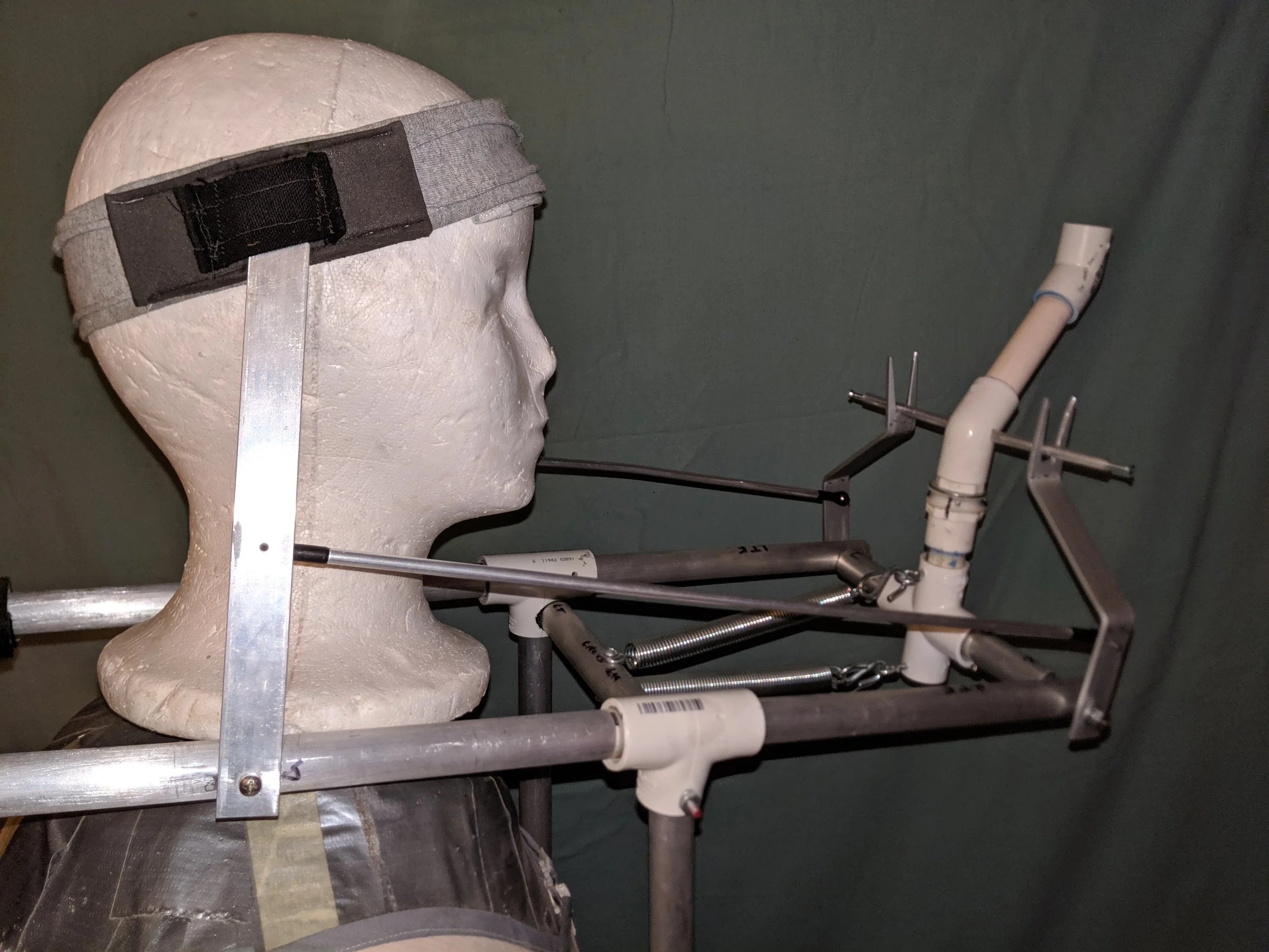
To clarify, this is how the headband connects my neck movements to the eye stalk